Quick contact →
- Tel.: +420 736 291 829
- E-mail: info@speltronic.cz
 The dynamometer is designed to test the parameters of electric motors. It is able to test not only direct current motors (DC) but also brushless motors (BLDC) for which an electronic driver is required.
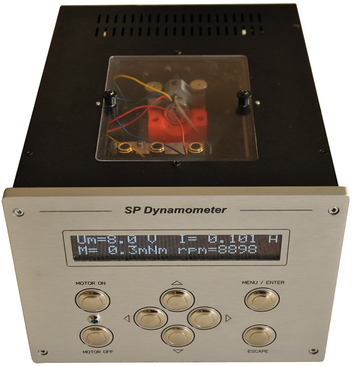
The main component of the dynamometer is a calibrated electrodynamic brake that simulates the load on the engine. The motor under test is attached to via a mechanical coupling. This is then connected to the dynamometer control electronics.
The dynamometer has two operating modes. In manual mode, the dynamometer operates completely autonomously and is controlled only by buttons on the control panel. This mode is used to test the engine once. In automatic mode is the dynamometer connected via USB interface to a computer. In the PC application it is then possible to perform multiple tests with the generating of a measurement report including graphical outputs.
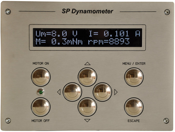 On the front panel of the dynamometer the user sets the parameters for the manual mode designed for single engine test.
In the automatic mode the buttons are blocked, except for the up and down arrows which toggle the parameters displayed on the screen.
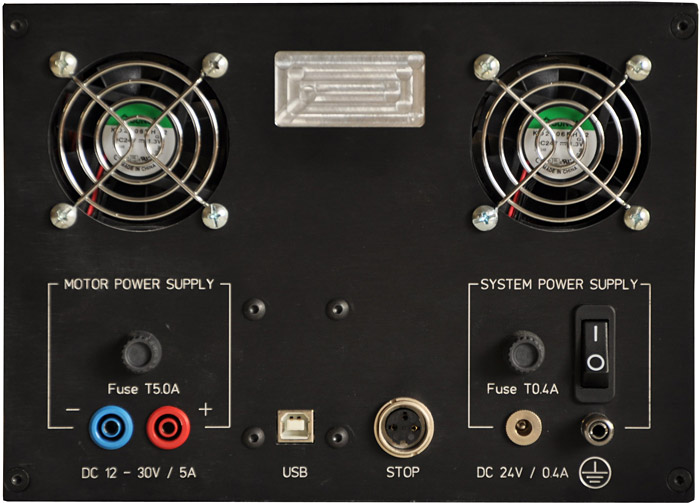 The rear panel of the dynamometer is equipped with fans that serve to dissipate heat from the interior of the dynamometer. There are also connectors for the external motor power supply, for communication with the computer via USB, power supply for the electronics, ground terminals and a safety STOP button.
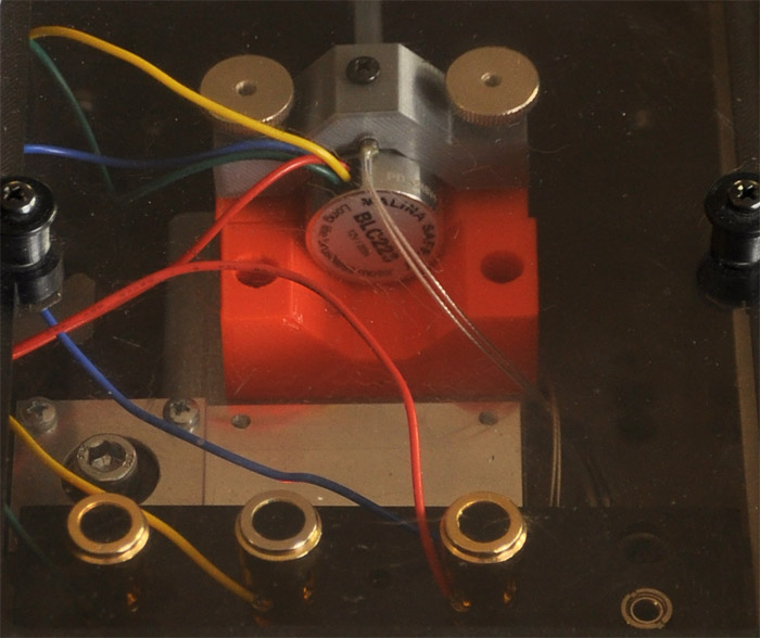 On the top panel of the dynamometer there is a space to place the motor under test. There are 3 terminals for BLDC and 2 for DC motors. The motor is attached to the electronic brake using a special coupling. The type of coupling is selected according to the size of the motor shaft diameter.
The correct connection of the motor under test is indicated by two LEDs in the upper window of the dynamometer.
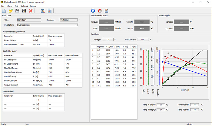 We have developed the MotorTester application which is used to control the dynamometer in automatic mode. After connecting the motor under test to the dynamometer, the user selects the type of electronic driver, enters the motor parameters provided by vendor (voltage, maximum motor current), sets the desired torque range and number of values.
The test then runs completely automatically, the application itself controls the entire test. At the end, it is possible to save all measured values to a file, export them to a pdf report or print the report directly.